Inside Logic Gates - The Electronic Logic

How does electronic gadgets really have logic working in themselves ?
Its been so long I have written an article out of the Newbie Programmer Series. But somehow this is one of its part. I was about to write on using logic operators but I found that before diving into the usage of logic, we have to learn how logic works in electronic world.
Introduction to electronic logic
You have somewhere heard of Logic Gates. These are nothing but specially designed circuits that allow the circuit designers to use logic. Below, I am giving a simple layout of these gates just to show how they work. The actual circuits are complicated but I tend to keep everything simple on my site.
What do you need ?
It’s not a hard thing to understand how logic works in electronic circuits. All you need is to imagine the following things :
- A battery
- Some wires
- Some switches
- Some bulbs
- For digitalness, We say ‘1’ if bulb is on, and ‘0’ if bulb is off.
The Logic of ‘on’ and ‘off’
As said above, for a computer, on means 1 and off means 0. You can understand this easily with the below diagram.
Logic of on and off, 1 and 0, based on bulb glows or not.
The electronic Logic Gates
What you have learned above is a simple one. Just on and off. But we need to use the special compound logic like AND OR NOT. Lets discuss them one by one.
AND logic
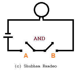
If you are using AND logic between two conditions, the AND logic says that to proceed further, both the conditions must be true. You can understand this with the pic below. It’s like to make the bulb ‘glow’, both the switches must be ‘on’.
The AND logic. Both A and B switches must be on, =1 to make the bulb glow.
You can see that when both A and B switches are on then only the process of glowing the bulb proceeds.
The Digital USE of AND:
If A = 1, and B is also = 1, then Z = 1. if any one of A or B is 0, Z = 0. You can check this by the AND Formula : A x B.
OR logic
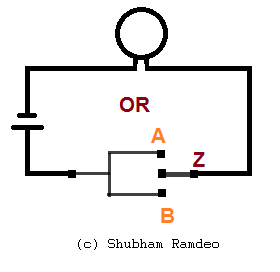
If you are using OR logic between two conditions, the OR logic says that to proceed further, at least one of the conditions must be true. You can understand this with the pic below. It’s like to make the bulb ‘glow’, at least one of the switches either A or B must be on.
The OR logic. Either A or B or Both should be ‘on’ ‘1’ to make the bulb glow
You can see that Z should be connected to either A or B or both. But in AND gate you have to connect both, here one is enough.
The Digital USE of OR:
Use OR formula : A + B, only when both A = 0, B = 0, Z = 0. Otherwise whenever atleast one of A or B is 1, A+B=Z becomes 1.
NOT logic
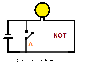
If you are using NOT logic, the NOT logic says that to proceed further, the condition must NOT TRUE. You can understand this with the pic below. It’s like to make the bulb ‘glow’, the switch A must not be ‘on’.
The NOT logic. When A is ‘on’ bulb goes ‘off’
You can see that if the Z switch is on, circuit will get shorted and bulb will not glow.
The Digital USE of NOT:
Its simple. Reverse of A. When A is off, Bulb is on. So If A = 0, Z becomes 1. Otherwise if A is 1, Z is 0. So Z is reverse of A. (simple ???)
These were basic circuits. Circuit designers connect them together to make more complicated logic. But to keep it simple so I think that’s enough. You can search for XOR, NOR, NAND gates which are nothing but using NOT gates together with the other gates. You can make your own logic. Stay connected for more.
Previous Chapter: « Relational OperatorsNext Chapter: Logical Operators »


